Shop
Ch 3 - Practice
Ch 4 - Fuse Bulkheads
Ch 5 - Fuse Sides
Ch 6 - Fuse Assy
Ch 7 - Fuse Exterior
Ch 8 - Headrests, Heat duct
Ch 9 - Main Landing Gear
Ch 10 - Canard
Ch 11 - Elevator
Ch 12 - Canard Install
Ch 13 - Nose Gear
Ch 14 - Centersection Spar
Ch 15 - Firewall
Ch 16 - Control System
Ch 17 - Trim
Ch 18 - Canopy
Ch 19 - Wings, Ailerons
Ch 20 - Winglets, Rudders
Ch 21 - Strakes, Fuel, Bags
Ch 22 - Electrical
Ch 23 - Engine
Ch 24 - Covers, Fairings
Ch 25 - Finishing
Ch 26 - Upholstery
Links
Contact
| Chapter 3 - Practice |
|||
| Chapter time: 1.5 |
Total Time: N/A |
||
Chapter
three is dedicated to builder education and the some practice layups
that demonstrate each of the methods and techniques used in
construction of the airplane. These layups are also quantifiable
such that you can qualify that you are doing things correctly.  The first layup is simply six plies of bi-directional (BID) fiberglass cut in a rectangular shape and laid up flat on top of one another. This is to ensure that "squeegee-ing", and "stippling" techniques are done properly, and that you can gauge the right amount of epoxy to properly wet out each layer of a layup. This layup is very straightforward. Being my first experience with MGS epoxy, I didn't know what to expect. I elected to start with a 50/50 mix of fast and slow hardener, which produc 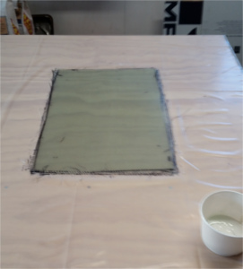 es
a 60-90 minute pot life, and takes 16-20 hours for a full cure.
Despite having ample time to work with the epoxy, and I made a total of
four separate small batches during the layup, I still worked a little
too fast, based on my previous experience with faster epoxies.
This did result in some small air bubbles in the lower layers. I
wasn't sure if that is what I was seeing while I was working, but
confirmed it during the final examination. Based on the
specification of no more than 10% of any area of the layup with
entrained air, this piece was marginal, but again, that is why it is
practice. After bird-dogging the layup for several hours
afterwards, I realized that there is plenty of time to work with the
epoxy before it sets, and I can also produce mixes with a single pot
life of 4-6 hours if needed. es
a 60-90 minute pot life, and takes 16-20 hours for a full cure.
Despite having ample time to work with the epoxy, and I made a total of
four separate small batches during the layup, I still worked a little
too fast, based on my previous experience with faster epoxies.
This did result in some small air bubbles in the lower layers. I
wasn't sure if that is what I was seeing while I was working, but
confirmed it during the final examination. Based on the
specification of no more than 10% of any area of the layup with
entrained air, this piece was marginal, but again, that is why it is
practice. After bird-dogging the layup for several hours
afterwards, I realized that there is plenty of time to work with the
epoxy before it sets, and I can also produce mixes with a single pot
life of 4-6 hours if needed. I covered the work table in 4 mil plastic. Despite ironing it out some, the creases in the plastic did transfer to the completed fiberglass part. Mostly a cosmetic issue, but in the future I will be getting plastic in unfolded rolls for this purpose. The plastic did a great job of releasing from the part though, and made cleanup very easy. I was very pleased with the performance of the epoxy box. I was able to meter resin and catalyst down to the gram. I had feared that the 3/8" ball valves would be too large to control the flow easily, and that they might drip a lot afterwards. They were suprisingly easy to control, and I didn't have to open them much beyond 30 degrees, which is barely opening the ball. I suppose that is why I didn't have any dripping either, as there was not enough flow to touch the threads in the valve end, rather it drained directly from the ball to the cup. The original layup is approximately 12.5" x 18". This allows for rough edges and misalignment of the edges of the layers. Once the composite has cured, it is cut to exactly 10" x 16" then weighed. The purpose of this is to determine if the appropriate ratio of epoxy to fiberglass is used. Too little epoxy creates a "dry" layup, and results in a lower strength part. Too much epoxy is not as detrimental structurally, but incrementally adds weight to the aircraft, which decreases capacity and performance. It has been estimated that too much epoxy as a result of improper layups can add 40 - 100 pounds of extra weight to a finished aircraft. When the usable load rating of the aircraft is @1000 pounds, this is reduced pound for pound for any weight of the aircraft over the prescribed empty weight. 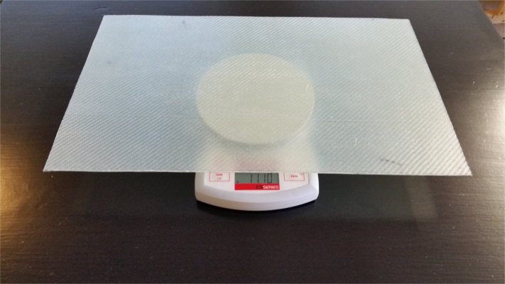 For the 10" x 16" 6-ply composition test coupon, the specified allowable weight is 10.5 Oz. - 12.5 Oz. The final weight of my test coupon after trimming was 11.10 Oz. so it was essentially perfect with respect to epoxy to fiberglass ratio. Despite having some entrained air, which is simply a matter of technique refinement, this initial test passed, and we will proceed with production of the second practice layup. |
|||
| 03/18/2016 - The
second layup is the confidence layup, which adds a foam core to the
fiberglass epoxy composite to create a small structural "beam".
The beam is then "tested" by placing it over a rounded object such as a
broomstick or small pipe, then standing on either side of it whereas it
should not break, demonstrating the strength of sandwich fiberglass
composite construction. When a 200 pound person stands on it (or
me holding a 20lb weight because I am only 180lbs), it represents a
force on the beam equivalent to a force of 10Gs on the airframe.
Since the aircraft is designed to operate in the utility category, the
maximum allowed load factor is 4.4Gs, so this layup demonstrates
strength in the construction that exceeds that which it should ever be
subjected to. This piece of foam is the centerpiece of the confidence layup. It is very fragile. I can easily snap a piece of it this size in half just holding it in one hand. I can scratch large chunks out of it with just my fingernail. By itself, it is flimsy, weak and fragile. 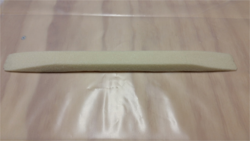 My confidence layup was a lot better in quality than the previous one. There was virtually no entrained air. Adding foam to the mix also adds another component, micro slurry, which is a mixture of epoxy and glass microspheres, which are microscopic glass spheres that appear like confectioner's sugar. Micro slurry is used anywhere foam and fiberglass meet. It helps to fill the small voids in the surface of the foam, and provide a greater surface area for the adhesion of the glass and epoxy to the foam. It is also used as a finishing filler on surfaces to be painted. 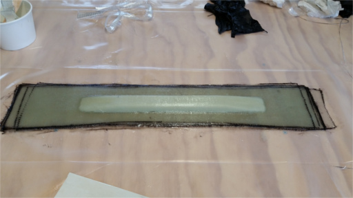 I use a Rigid brand oscillating tool to cut cured fiberglass. I drew the lines for trimming the beam on the bottom and clamped it to the table upside down so I could follow the lines. After trimming I noticed a couple of abraded places where the fiberglass was against the table. Apparently the oscillating tool created enough vibration between the part and the table to abrade the fiberglass. The abrasions were minor, but i'll have to remember this when cutting future pieces to prevent damage. 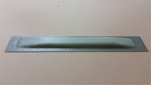 And now for the test:
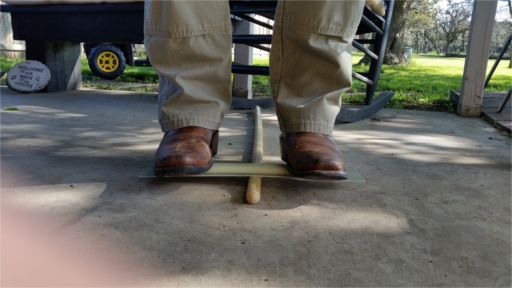 Yes, that's me standing on the beam built during the confidence layup. The same piece of foam shown above now has 180 pounds balanced on it over a broomstick. Encased in fiberglass and epoxy, the composite structure is much stronger. The beam is not touching the ground on either side. The beam bends slightly, but returns to its original shape immediately after I step off of it. There are no stress marks, scratches, cracks or any evidence of damage to the part. According to the plans, a 200 pound person standing on the beam over a broomstick like this excerts a force equivalent to what 10Gs of force would exert on the aircraft, so this is a very good demonstration of the strength and durability of the materials used to construct the MKIV. < PREVIOUS PAGE NEXT PAGE > |
|||